Static dischargers are use to reduce precipitation static discharge interference to aircraft radio communications and navigational systems.
For maximum effectiveness, static dischargers are installed at the aircraft trailing edges extremities, (wing, horizontal stabilizer end caps, and tail). According to SAE ARP 5414, these extremities are designated as lightning zone 1. Components located in zone 1 are susceptible to the full force of a direct lightning strike. Lightning current components (A, B, C, & D) associated with zone 1 will cause severe damage to the discharger installation components and/or aircraft structure if not properly protected. The most outboard trailing discharger has the highest electric field concentration and is most critical to the system. It dissipates most of the discharge current and generally receives the worst lightning damage. The extend of damages varies, and depend upon the construction and design of the discharger.
Dayton-Granger, Inc. has developed a lightning survivable discharger (Null-Strike PN 16785) that protects and minimizes lightning damages to the aircraft trailing edge structure.
Null-Strike Static Discharger
The 16785 is a Null-Strike high performance trailing edge static discharger designed for commercial and business class aircraft with speed up to 600 knots. It consists of a metal shank into which a distributed resistive element is inserted. The resistive element has a semi-conductive carbon discharge point for optimum noise quieting and is equipped with a special thermo-fit shrink tubing to protect it against rain erosion.
It is lightweight, aerodynamically designed to reduce drag, and has stable resistance from -65°C to +125°C. It incorporates DG special “STRIKEGUARD” lightning diverter element, which is used to divert lightning strikes and thus minimize lightning damages to the aircraft trailing edge.
The Strikeguard diverter element is composed of finely deposited aluminum oxide particles epoxied to the outside surface of the discharger body. The electrical characteristics are such that it represents an open circuit at DC potentials and a short-circuit at voltage levels experienced during a lightning strike. Lightning striking the discharger will be diverted to the metal shank via the ionized path created by the aluminum oxide particles.
This conduction reduces the chance of lightning damaging the aircraft trailing edge.
Lightning Attachment Process
Static dischargers are positioned where the aircraft is most likely to go into corona (wing tips, vertical and horizontal stabilizers).
As the lightning step-leader approaches the wing tip, streamer currents will flow from the aircraft metal structure to the discharger tip through the resistive element. The leader will make contact with streamers from several dischargers and from several ionized lightning channels. The most outboard trailing discharger has the highest electric field concentration and therefore, the strongest streamer. A large percentage of lightning current is transfer to the discharger installation components (Shank/Retainer). Because of its high-resistance, the voltage potential at the end of the resistive element is high enough to ionize the surrounding air gap. Once the ionized channel is established, most of the lightning current is transfer through the ionized channel, bypassing the resistive element. When the transfer occurs, the external surface of the resistive element is exposed to severe heat that cause physical damage to the discharger. The most outboard trailing discharger generally receives the worst damage. The extent of damages varies, and depends upon the construction and design of the discharger. For example, composite dischargers are severely damage by the high coulomb content of the lightning continuous current component.
The Strikeguard element on the 16785 guides the lightning current to the grounded metal shank without any physical damage to the discharger. On the Null-Strike 16785, the discharger and mounting retainer remains intact. Electrical characteristics such as resistance, RF noise quieting and discharge current remains normal, and within specification.
Static Discharger Installation
The most outboard discharger is most critical to the protection system, and must be position near the tip of the trailing edge as possible. For best protection, the discharger should be install in such a manner that the aft edge of the metal-shank is positioned as far away from the aircraft trailing edge as possible. The metal shank is design to confine lightning current “burning and erosion” damages to the discharger itself, thus protecting the aircraft trailing edge structure. Laboratory lightning tests revealed that dischargers with metal shanks extending
approximately 2-inches beyond the aircraft trailing edge are sufficient to protect aircraft trailing edge structure from direct lightning burning and erosion damages. The best design for lightning survivability is the combination of (Strikeguard diverter with Metal Shank). A discharger is more likely to survive if it includes a long metal shank. Dischargers with short metal shank will terminate the lightning channel at the aircraft trailing edge. Dischargers with long-metal shank will terminate the lightning channel at the metal shank, thus minimizing damage to the airframe. DG Null-Strike (16785) has a 2-inch long metal shank that withstands zone 1 currents.
Dischargers are generally installed on the trailing edges of wings and tail surfaces where the electric field is high. The discharger should be installed so that the tip trails away at a maximum distance from the edge. The outer most discharger should be installed at the point where the trailing edge begins curvature to the extreme tip. It should also be aligned with the normal air stream. Dischargers should be separated by 12 to 24 inches. Closer spacing results in reduced currents due to mutual shielding and farther spacing results in decreased overall effectiveness because of the drop in gradient as the fuselage is approached.
Discharger Lightning Survivability Test
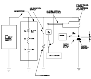
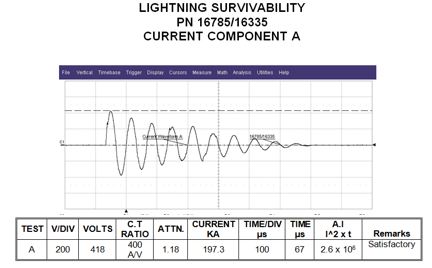
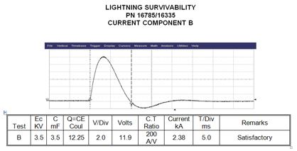
DG 16785 Null-Strike discharger and trailing retainer PN 16335 were tested in accordance with MIL-DTL-9129F, Section 3.6.16 and 4.6.14. The assembly was subjected to lightning zone 1A current (component A and B) per RTCA/DO-160D, Section 23. The discharger was mounted on a 12″ x 12″ x .08” thick aluminum plate, with appropriate mounting screws. The electrode was positioned approximately ½ inch above the discharger metal shank. A No. 30 copper wire was used in the gap to assist in the current discharge. Current waveforms A and B were applied to the assembly.
A sketch of the test configuration is shown in Figure 1,
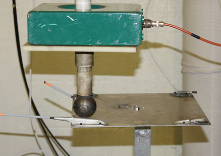
and a photograph of the test set-up is presented in Figure 2.
Recording of applied current waveforms A and B is presented in Figures 3 & 4.
To be classified as a lightning survivable discharger, the discharger and retainer must remain intact and meet the requirements for discharge current, RF noise, and dc resistance.
Results
The discharger and retainer assembly remained intact and the post-test resistance, discharge current and RF discharge noise were within the specified limits. A summary of the test results is shown in Tables 1 & 2. The dischargers/retainers passed the Lightning Survivability test. The 16785 meets the requirement for a lightning survivable discharger.
Table I – Pre-test Results
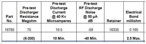
Table II – Post-test Results
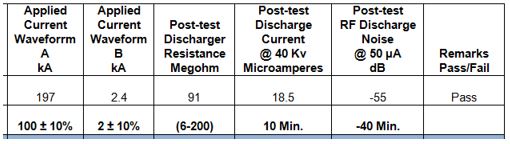
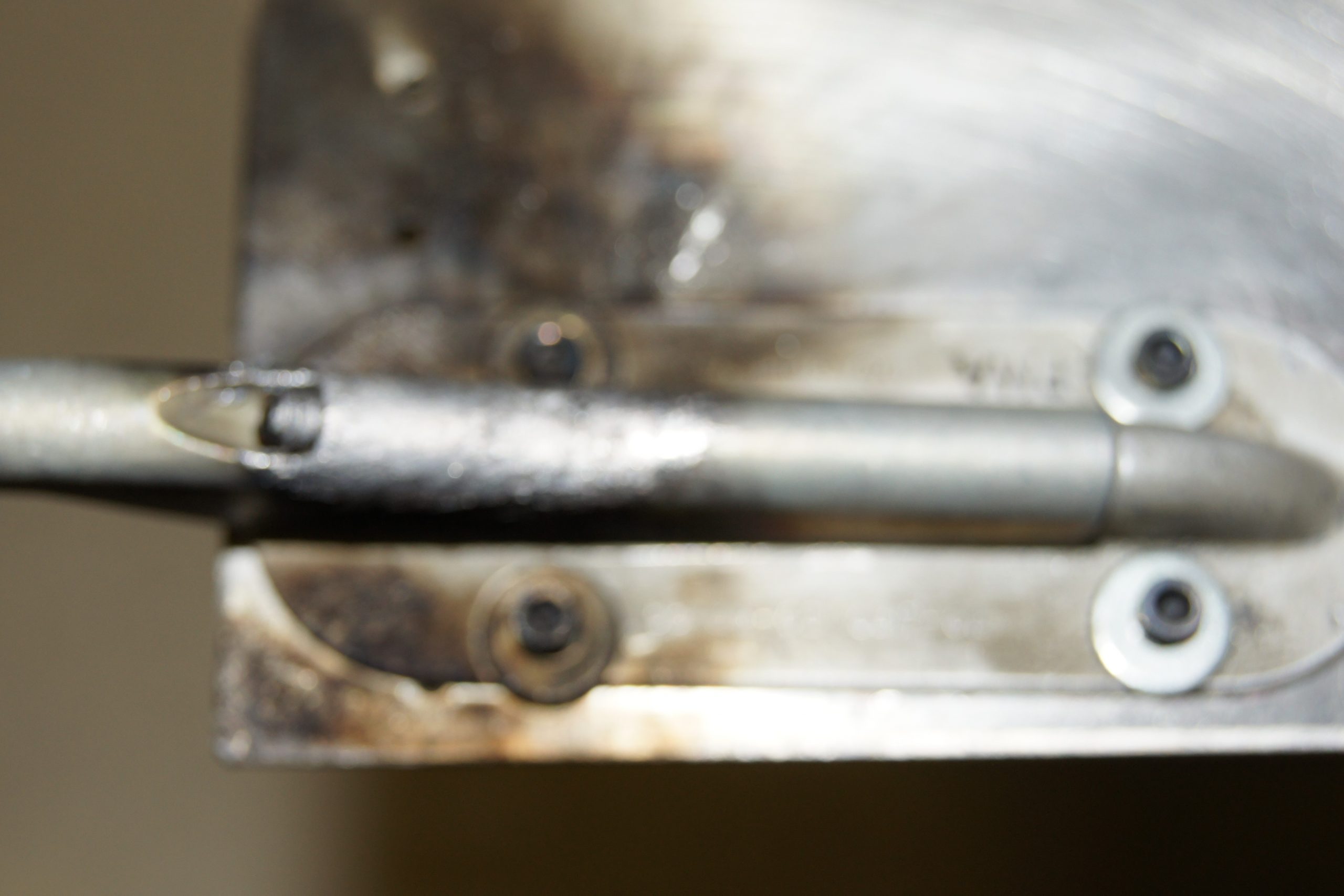
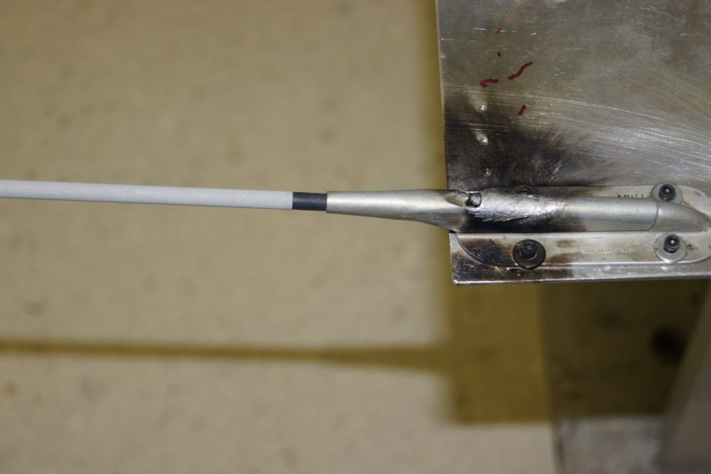
Photo of Damages: